Choosing a sheet metal cutting machine is rarely a simple matter of comparing prices and motor power. The right choice depends on material thickness, production volume, cutting accuracy, workshop space, and operator skill. A machine that performs well on thin stainless steel may struggle with thick carbon steel. Small details matter, including nozzle alignment, extraction capacity, software compatibility, and service response.
Dr. John G. Lenard, a respected sheet-metal forming specialist, has emphasized, “The quality of a part is determined by the process, not by inspection alone.” This principle applies directly to machine selection. A reliable sheet metal cutting machine should create clean edges repeatedly, not only during a supplier demonstration. Examine sample cuts closely. Look for burrs, heat discoloration, rough corners, or uneven kerfs. Ask whether the machine can maintain accuracy after several hours of operation.
The following ten tips focus on practical decisions rather than impressive brochures. They cover cutting technology, material requirements, automation, safety, maintenance, operating costs, and supplier support. Do not ignore the uncomfortable questions. Can your team learn the controls quickly? Is replacement tooling available locally? What happens when production stops on a Friday evening?
No machine is perfect.
A careful buyer should also admit uncertainty. Future materials may change. Order sizes may fluctuate. A cheaper machine might become expensive through downtime and wasted sheets. Conversely, advanced automation may exceed a small workshop’s actual needs. The best decision balances present evidence with realistic growth, verified specifications, operator feedback, and long-term reliability.
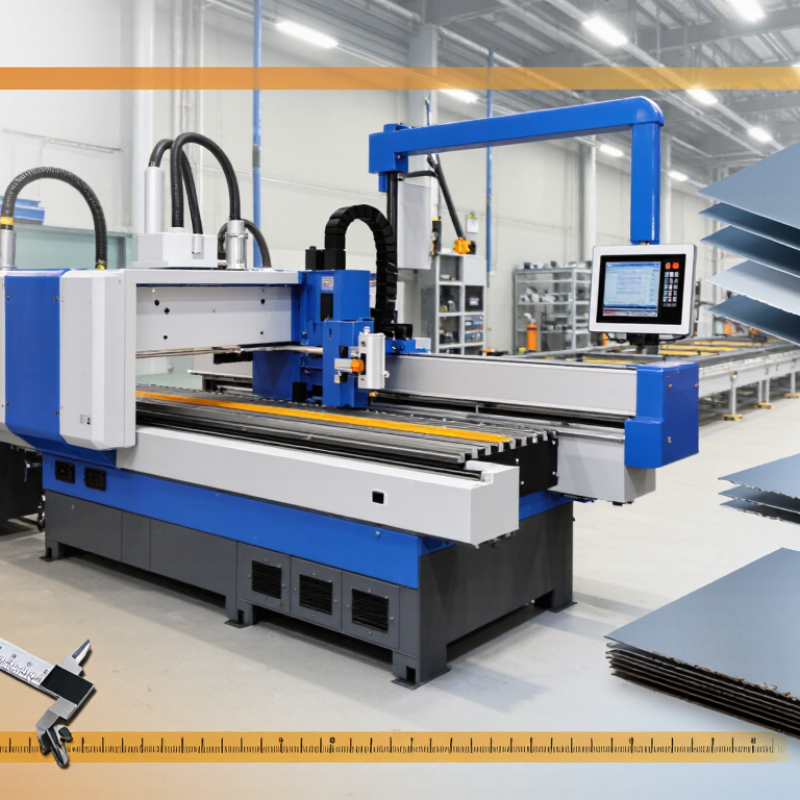
Define the material before comparing machine specifications. Mild steel, stainless steel, aluminum, and copper react differently during cutting. Their hardness, reflectivity, and thermal conductivity affect edge quality. Your target range should cover 0.5–25 mm, not just your most common sheet. Thin 0.5 mm stock can warp from excessive heat. Thick 25 mm plate may require slower travel and stronger cutting capacity.
Tip: List each material, thickness, sheet size, and monthly volume. Then separate routine work from occasional jobs. A machine that handles 25 mm steel may not produce clean edges on delicate aluminum. For ±0.1 mm tolerance, inspect the machine’s repeatability, motion stability, kerf control, and calibration process. Confirm how accuracy is measured, because “precision” can mean different things.
In practical testing, cut a small batch using your actual material. Measure holes, slots, and outside dimensions with calibrated tools. Check the first and last parts, not only the easiest sample. Temperature, nozzle condition, vibration, and sheet flatness can change results. I have seen a technically capable machine miss tolerance after poor setup. That mistake is easy to overlook. Allow time for maintenance and operator training. A narrow tolerance also needs a realistic inspection plan.
Choosing a sheet metal cutting machine starts with wavelength, not advertised wattage. Fiber lasers operate near 1.06 µm, while CO₂ lasers emit near 10.6 µm. That difference changes absorption, speed, heat input, and operating cost.
For mild steel, stainless steel, and aluminum, fiber technology usually couples energy more efficiently. Industrial energy assessments commonly report wall-plug efficiency near 25–35% for fiber systems, compared with about 8–15% for CO₂ systems. The Fraunhofer Institute for Laser Technology has reported similar efficiency advantages in industrial processing studies. Fiber also needs less optical maintenance, which matters during long production shifts. A 3 mm stainless-steel sheet can leave a bright, narrow kerf when focus and gas pressure are correct. Small settings matter.
CO₂ remains useful for nonmetallic materials and some demanding thick-section applications. Its longer wavelength interacts differently with reflective metals, especially aluminum and copper. Fiber often handles these metals better, but excessive power can create dross and a rough lower edge. That mistake is common. The International Energy Agency reports that industry consumes roughly 37% of global final energy, so electrical efficiency deserves attention beyond purchase price. Check thickness ranges, pierce time, assist-gas consumption, duty cycle, and service records. ISO 11553-1:2020 also supports a formal approach to laser-processing safety. A practical test cut on your actual alloy may reveal more than a polished specification sheet.
| Tip | Selection Factor | Fiber Laser Approx. 1.06 µm |
CO₂ Laser Approx. 10.6 µm |
Practical Recommendation |
|---|---|---|---|---|
| 1 | Match the wavelength to the material | Near-infrared wavelength; generally well suited to steel, stainless steel, aluminum, brass, and copper when the machine is properly configured. | Far-infrared wavelength; commonly effective on carbon steel, stainless steel, aluminum, and many nonmetallic materials. | Start with the material mix and thickness range, not laser power alone. |
| 2 | Check reflective metals | Typically offers a practical advantage on copper and brass because the shorter wavelength is absorbed more effectively than 10.6 µm radiation. | Highly reflective metals can send energy back toward the cutting head and optical path, requiring suitable protection and process controls. | For frequent copper or brass production, confirm reflected-beam protection, cutting data, and warranty requirements. |
| 3 | Evaluate thin-sheet productivity | Often provides high cutting speeds on thin and medium-gauge sheet, especially in automated production environments. | Can cut thin sheet effectively, but speed comparisons depend on power, nozzle, gas, focus, material grade, and part geometry. | Request a timed test using representative parts instead of relying on published maximum speed. |
| 4 | Consider thick-plate capability | Can process thick metal, but the usable range varies significantly with rated power, beam quality, assist gas, and machine rigidity. | Has long been used for a broad range of metal thicknesses; high-power systems may be selected for demanding thick-section work. | Define the maximum production thickness and required edge quality before selecting rated power. |
| 5 | Review edge quality requirements | Can produce narrow kerfs and precise detail on many sheet metals, with results strongly affected by focus position and cutting parameters. | Can deliver high-quality edges, particularly when the optical path, beam mode, focus, and gas settings are correctly maintained. | Inspect dross, taper, heat-affected zone, and surface roughness on actual production materials. |
| 6 | Compare electrical efficiency | Solid-state architecture generally converts electrical input to laser output more efficiently than conventional CO₂ architecture. | Typically requires more electrical power for the same optical output and also needs cooling for the resonator and gas system. | Estimate total operating cost from actual duty cycle, electricity, cooling, gas, optics, and maintenance. |
| 7 | Assess maintenance needs | Usually has fewer beam-delivery components and no resonator gas mixture, which can simplify routine maintenance. | Uses mirrors, a beam path, resonator components, and gas-related systems that require alignment, cleaning, and scheduled service. | Compare service intervals, spare-part availability, technician skills, and preventive-maintenance procedures. |
| 8 | Select assist gases carefully | Nitrogen is commonly used for bright, oxidation-minimized edges in stainless steel and aluminum; oxygen can increase cutting speed in carbon steel but creates an oxidized edge. | Uses oxygen, nitrogen, or air depending on material, thickness, edge appearance, and machine setup. | Include gas consumption, pressure, purity, storage, and post-cut finishing in the cost calculation. |
| 9 | Check optics and safety requirements | Requires optics and an enclosed cutting area suitable for near-infrared radiation; reflected energy from shiny metals must be managed. | Requires infrared-rated enclosures, beam-path protection, clean mirrors, and correct alignment procedures. | Verify enclosure classification, interlocks, viewing windows, fume extraction, and operator training before installation. |
| 10 | Test the complete production workflow | Often integrates well with automated loading, unloading, nesting, and high-throughput sheet production. | Can support automation and large-format processing, with workflow performance dependent on machine layout and handling equipment. | Measure cut time, loading time, setup time, scrap rate, uptime, and finished-part quality in a realistic trial. |
10 Tips for Choosing a Sheet Metal Cutting Machine
Compare Power and Cutting Speed Across 1–6 kW Machine Classes
Power is not cutting speed by itself. A 1 kW fiber machine may cut 1 mm mild steel at roughly 12–20 m/min. A 6 kW model may reach 35–60 m/min under similar conditions. These are practical ranges, not promises. Gas pressure, nozzle design, focus position, and material quality can change the result. Tip: Request timed cuts using your actual sheet grades. A showroom sample can mislead.
The 2–3 kW class often suits mixed fabrication work. It balances investment, electricity use, and moderate thickness. Machines from 4–6 kW improve throughput on thicker carbon steel and stainless steel. However, higher power can increase piercing heat, maintenance demands, and energy consumption. The U.S. Department of Energy’s Industrial Decarbonization Roadmap reports that process heat represents about 51% of industrial energy use. The International Energy Agency also identifies industry as a major share of global final energy demand. Tip: Compare parts per hour, not only rated kilowatts.
Cut quality needs measurement. Check edge angle, burr height, heat marks, and hole accuracy against ISO 9013 guidance. Tip: Ask for test coupons and inspect the underside. I would not trust a speed chart without material certificates. Reflect on your real workload, too. A 6 kW machine running below capacity may be wasteful. A 1 kW machine missing deadlines is costly. Record cycle time, scrap, electricity, and operator adjustments for one full production week.
10 Tips for Choosing a Sheet Metal Cutting Machine
Verify Kerf, Work Area, and Positioning Accuracy: 1,500 × 3,000 mm
A 1,500 × 3,000 mm work area suits many standard sheet formats, but the usable area may be smaller. Check clamps, edge clearance, loading space, and the real cutting envelope. A machine may accept a full sheet yet lose 20–50 mm near its edges. Measure it during a trial, not only from the specification sheet.
Kerf width affects nesting, corners, and final dimensions. It changes with material grade, thickness, gas pressure, focus, nozzle condition, and cutting speed. ISO 9013 provides quality classifications for thermally cut surfaces, so request test samples against a defined class. The 2024 World Steel Association outlook projected global steel demand at about 1.77 billion tonnes in 2025, increasing pressure for stable throughput and lower scrap.
Positioning accuracy also needs careful interpretation. ISO 230-2 separates positioning accuracy from repeatability and reversal errors. Ask for measured data across the full 3,000 mm axis, not one central point. Test several X and Y locations, then repeat the cuts after thermal expansion. Small errors accumulate.
Do not trust perfect brochure numbers. A 0.01 mm claim may describe repeatability under controlled conditions, not production accuracy. Record kerf compensation, corner overshoot, and actual part dimensions. That extra checking feels slow, but it can expose weaknesses before they become expensive habits.
Choosing a sheet metal cutting machine requires more than comparing purchase prices. Calculate its five-year cost before signing an order. Include electricity, consumables, maintenance, labor, downtime, and expected resale value. A cheaper machine can become expensive when it runs slowly or wastes material.
Measure actual production conditions. Record daily operating hours, sheet thicknesses, cutting speeds, and average power consumption. Then estimate energy costs using your local electricity rate. Consumables include nozzles, lenses, filters, cutting gases, and replacement parts. Keep a realistic allowance for price increases. Small items often create large annual expenses.
Uptime deserves careful attention. One unexpected stoppage can delay several orders and add overtime costs. Ask for documented service response times, preventive maintenance schedules, and spare-part availability. Calculate the hourly value of your production line, then multiply it by expected downtime. My own early estimates were too optimistic because they ignored setup changes and operator training. That mistake changed the investment decision. Use conservative assumptions, not ideal factory figures. Finally, estimate ROI from additional saleable output, lower scrap, reduced labor, and faster delivery. Divide the total gain by the five-year ownership cost. Recheck the calculation with your maintenance supervisor and machine operator. Their practical observations may expose costs hidden in a spreadsheet.
This planning model compares representative machine configurations without using company or brand data. Costs are shown in USD thousands and include acquisition, electricity, consumables, maintenance, and production downtime over five years.
Assumptions: 2,000 cutting hours per year, industrial electricity at $0.12/kWh, downtime valued at $100 per hour, and regular preventive maintenance. Modeled ROI is calculated as (five-year gross contribution − five-year total cost) ÷ initial acquisition cost. Actual results will vary with material thickness, utilization, labor, local energy prices, and service rates.